In daily network deployment scenarios, directly pulling out Ethernet cables from wall points, crimping RJ45 connectors and connecting them to switches can meet the temporary access requirements of one or two terminal devices. However, as the usage scenarios expand, such as adding a new room, connecting the fourth or fifth device, or even adding a PoE camera that requires power supply, the number and routing of cables will gradually become complex. At this point, if the cables are not clearly labeled, once a device malfunctions, you may have to spend a lot of time checking one by one and repeatedly plugging and unplugging, which may delay the quick location and resolution of the problem. In contrast, using a Wall Mounted Patch Panel can achieve centralized, structured termination and labeled management of cables, not only significantly improving daily management efficiency, but also enhancing network maintainability and operation and maintenance efficiency.
A wall mount patch panel is a fixed termination point that gathers all your permanent cable runs into a single, labeled and easily accessible location. With a patch panel, all runs end at the panel. Short patch cords connect the panel to your switch. And when a port needs to move to a different device, you only need to swap a patch cord. The cable in the wall always stays put.
Today, we’ll see what a wall mount patch panel is, how it fits into a structured cabling system, which components you need, and how to install it step by step.
What Is a Wall Mount Patch Panel?
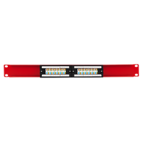
A wall mount patch panel is a network hardware assembly, designed to be mounted onto a wall or other vertical surface, serving as a centralized termination point for the Ethernet cables running through your walls and ceiling into a row of labeled, front-facing ports.
All ports on the front accept standard RJ45 patch cords; at the rear of the panel, is where each permanent cable is terminated. Cables can be terminated either by punching individual conductors into insulation displacement contacts (IDC) or into pre-terminated keystone jacks.
With an insulation displacement contact, or IDC, the metal slot cuts the conductor insulation and makes contact with the copper wire. This means you don’t need to strip the individual wires. You simply press the conductor into the slot with a punch-down tool, and the blade seats the wire and trims the excess. The keystone format works differently: you terminate each conductor into a separate modular jack, then snap the jack into the panel frame.
Before buying, you need to look at the port count.
- A 12-port wall mount patch panel is usually enough for most small offices or residential installations with up to 12 drops.
- A 24-port panel covers larger homes, small commercial spaces, or installations where future expansion is expected.
Both formats mount to a standard 19-inch rack frame and occupy one rack unit (1U) of vertical space.
What is the difference between a patch panel and a network switch?
A patch panel has no active electronics. It doesn’t route traffic or manage network connections. It is passive hardware whose role is to terminate permanent cable runs and present them as labeled, accessible ports.
A network switch, on the other hand, is an active device that connects to the patch panel through short patch cords. It handles all data routing.
While the panel organizes your permanent infrastructure, the switch manages your network.
Expert Tip: If you need to replace your switch, having a patch panel means you won’t need to perform any re-termination. You unplug the patch cords, swap the switch, and plug them back in.
How Wall Mount Patch Panels Fit into Structured Cabling
A wall mount patch panel is at the equipment end of a structured cabling channel, where it terminates the permanent link and connects it to your active hardware.
Within a structured cabling system, as ANSI/TIA-568-E defines it, the horizontal cabling runs from a telecommunications room or equipment area to a work area outlet. The panel is the termination point on the equipment side, and the keystone jack or wall plate port is the termination point on the work area side. Patch cords bridge both ends to active devices.
Per ANSI/TIA-568, the fixed cable run from panel to wall port (the permanent link), must not exceed 90 meters (295 ft). The total channel, including patch cords, must not exceed 100 meters (328 ft). This means your total, combined patch cord length can be up to 10 meters across the whole run. For example, if you have a 3-meter patch cord going from the panel to the switch and a 3-meter patch cord from the wall port to a laptop, you are using 6 meters of that allowance. The importance of staying within these limits is to maintain expected link performance at Gigabit and 10 Gigabit speeds.
The patch panel also separates two parts of the network that have different functions.
The permanent cabling in the wall is fixed infrastructure, designed to last for years or decades. The patch cords in front of the panel are the flexible layer; you change them when you need to move devices or have new requirements. Moves, additions, and changes (MACs) take place at the panel, not inside the wall.
If your installation includes Power over Ethernet (PoE) devices (cameras, access points, or VoIP phones), the patch panel is part of the thermal path. PoE delivers power and data over the same cable at the same time. Higher-power PoE standards use all four cable pairs, increasing current through every conductor and every contact in the channel. In high-density PoE installations with many bundled cables, heat builds up within the bundle.
Bundled cables don’t disperse heat as efficiently as open runs. Check whether your panel and keystone jacks carry an explicit PoE rating that covers the power class your devices draw.
Expert Tip: For any PoE++ (IEEE 802.3bt Type 3 or Type 4) run, verify that the patch panel, keystone jacks, and patch cords are all rated for the power level. A mismatched component anywhere in the channel becomes a failure point under sustained load.
Components
A complete wall mount patch panel setup contains five main elements. The panel is the core, and the other components make it functional, serviceable, and code-compliant.
The five components are the patch panel, the wall-mount enclosure or rack, the bulk cable, the patch cords, and the cable management accessories. Each one plays a distinct role in the finished installation.
- The patch panel. It’s the core hardware. It accepts cable terminations on the rear and presents labeled RJ45 ports on the front. Punch-down panels use IDC contacts and require a 110-style punch-down tool for termination. Keystone panels accept pre-terminated modular jacks that snap into the frame. Toolless keystone panels allow field termination without a punch-down tool, which suits home installations and small office work where specialized tools may not be available. For high-volume structured cabling work, punch-down panels are the standard choice because they seat all conductors consistently across many terminations.
- The wall-mount enclosure. This is the housing that holds the panel, your switch, and any other rack-mount gear. Open swing-gate racks bolt to studs or a backboard and allow the entire frame to hinge away from the wall for rear cable access. Enclosed cabinets offer more physical protection and a cleaner finish at the cost of ventilation. For home and small office installations, a 6U or 12U open swing-gate rack gives you enough space for a patch panel, a switch, and a cable manager bar, without requiring a full equipment room. Depth matters: confirm that your switch fits within the rack depth before purchasing.
- Patch cords. We refer to the short, flexible, stranded-conductor cables that connect the patch panel to the switch and the wall port to the device. Stranded conductors make patch cords more flexible than solid-core bulk cable, which makes them suitable for the frequent movement that happens at the equipment and device ends. Match your patch cords to your cable category. A Cat5e patch cord on a Cat6A run limits the link to Cat5e performance.
- Bulk cable. This is the solid, in-wall cable that forms the permanent link between the panel and each wall port. Solid conductors are the correct choice for fixed runs since they terminate cleanly into IDC contacts and hold consistent electrical properties over distance.
- Cable management accessories. We use them to keep the rear terminations organized and to protect the cables from sharp bends or physical stress. A 1U horizontal cable manager bar sits between panel rows in the rack and provides a routing path for patch cords at the front. Hook-and-loop fastener strips (preferred over zip ties for in-rack cable management) hold cable bundles without cutting into the jacket when tightened. A labeling strip or port labels on the panel face are the final piece. Label both the panel port and the far-end wall plate port before testing.
Expert Tip: Match the cable category to your panel and jacks. A Cat5e cable behind a Cat6A panel limits the link to Cat5e performance.
Which cable categories work with a wall mount patch panel?
Category 5e, Category 6, and Category 6A are the three categories you will find in most home and small office installations, and all three terminate directly into a standard wall mount patch panel using RJ45-format jacks and connectors.
Category 5e: Cat5e uses 24 AWG solid conductors, operates up to 100 MHz, and supports Gigabit Ethernet over runs up to 100 meters. Cat5e is adequate for most home networks running 1 Gbps today, although it leaves no room for 10 Gbps or high-power PoE deployments.
Technical note: American Wire Gauge, or AWG, is the US standard for measuring conductor diameter. The lower the number, the thicker the conductor.
Category 6: Cat6 uses 23 AWG solid conductors, operates up to 250 MHz, and supports Gigabit Ethernet over 100 meters and 10 Gigabit Ethernet on shorter runs, generally up to 55 meters. The thicker conductor gives Cat6 lower resistance than Cat5e, which is useful for longer runs and under PoE load. Cat6 is a practical baseline for new installations if budget is not a constraint.
Category 6A: Cat6A uses 23 AWG solid conductors, operates up to 500 MHz, and supports 10 Gigabit Ethernet over the full 100-meter channel. ANSI/TIA-568.2-D defines Cat6A as augmented Category 6. Cat6A is the right choice for any new structured cabling installation that expects to run 10 Gbps, serve PoE++ devices, or remain in service for 10 or more years. The cable is larger in diameter than Cat6, which means it needs more clearance inside walls and a slightly larger bend radius.
Category 7: Cat7 is specified by ISO/IEC 11801 as Class F, is not recognized by TIA, and when terminated with standard RJ45 connectors, which is the only practical option for most installations, its performance is capped at Cat6A levels.
Category 8: Cat8 is defined by ANSI/TIA-568.2-D, supports 25 Gbps and 40 Gbps, but is limited to a 30-meter maximum channel length, making it a data center cable with no practical application in residential or small office horizontal runs.
Expert Tip: If you are running new cable, install Cat6A. The price difference over Cat6 is small, and it provides the 10 Gbps capability whenever you need it.
Installation Steps
The key to correctly installing a wall mount patch panel is to follow a sequence of steps. Most wiring mistakes happen when the installer skips steps or does them in the wrong order.
The steps below follow the standard ANSI/TIA-568 structured cabling practice. So, simply follow them in order.
1. Plan and measure
Count your cable runs and confirm each one stays within the 90-meter permanent link limit.
Map the panel position to minimize total cable length. A centrally located panel reduces the chance of any single run approaching the limit.
Before you start terminating anything, write down which room or device each run serves.
2. Mount the enclosure
Locate wall studs or install a plywood backboard rated to carry the enclosure’s weight. Mount the swing-gate rack or enclosure at eye level for comfortable rear access during termination. Use a level.
Confirm that all mounting screws reach solid wood or anchor points rated for the load. Verify the enclosure has cable entry knock-outs or grommets aligned with the direction from which your cable runs arrive.
3. Route and dress the bulk cable
Feed each cable run into the enclosure through the designated entry points.
Leave enough slack at the panel end to reach any port across the panel face, plus a service loop of 300 to 450 mm (12 to 18 in) coiled behind the panel.
Maintain the cable's minimum bend radius (for Cat6A, at least four times the outer cable diameter).
Dress cables along the rear of the enclosure using hook-and-loop straps.
Separate any Cat6A bundles from line-voltage wiring by at least 50 mm (2 in) to prevent electromagnetic interference (EMI), which is noise induced by adjacent electrical fields.
4. Terminate each cable into the panel
Strip 25 to 40 mm (1 to 1.5 in) of outer jacket.
Keep the pairs twisted as close to the IDC contacts as the jack guides allow. Untwisting pairs beyond the jack's wire guides increases near-end crosstalk (NEXT), which is signal coupling between adjacent wire pairs.
For punch-down panels, use a 110-style punch-down tool set to cut mode so the tool seats the conductor and trims the excess in one stroke.
For toolless keystone panels, load each conductor into the cap's numbered channels matching your wiring standard, then press the cap closed.
Use T568B wiring pattern on every termination in the run. T568A is also acceptable if the entire system is wired consistently to T568A, but never mix the two patterns across the same channel.
5. Label every port and cable end
Label both the panel port and the corresponding wall plate port before testing. Use the same identifier at both ends, for example, "BR2" for bedroom 2.
Per ANSI/TIA-606, consistent labeling at both ends is the baseline for any serviceable cabling installation. Handwritten labels on tape are readable at first but degrade or fade quickly. Use a label maker or printed labels for permanent installs.
6. Add patch cords
Connect a patch cord from each panel port to the corresponding port on your switch. Use patch cords rated to the same or higher category as your permanent link. Keep each patch cord as short as practical. A patch cord draped loosely across the rack adds physical stress to the panel port and the switch port over time.
Route patch cords through the front cable manager bar to keep the rack face clear.
7. Test before closing
Use a wiremap tester on every run to confirm all eight conductors are correctly wired -pin for pin - at both ends. A wiremap tester sends a low-voltage signal through each conductor and confirms it arrives at the correct pin on the far end.
A pass result tells you the wiring is correct.
For PoE devices, use a PoE line-detection tester at the device end of the cable after powering up the switch. This confirms whether the port is delivering the expected power class.
Resolve any faults before installing wall plates or cable management covers.
How do you terminate cable into a wall mount patch panel?
It doesn’t matter whether you are using a punch-down panel or a keystone-format panel: the cable termination process into a wall mount patch panel is the same. The goal is the same in both cases.
Your goal is to seat all eight conductors in the correct positions with minimal untwist.
- Strip the outer jacket back 25 to 40 mm.
- Fan the four pairs apart and identify each by color: blue, orange, green, and brown, each with a solid-color wire and a white wire with a colored stripe.
- Follow the color-coded positions printed on the panel or jack body; most come labeled for both T568A and T568B.
- Keep each pair twisted until it enters the contact.
- For punch-down panels, press each conductor into its labeled slot with the cut side of the blade facing outward.
- Apply firm downward pressure until the tool clicks. For toolless keystone jacks, load each conductor into the numbered channel on the cap, then press the cap closed until it seats.
- Trim any conductor end that extends past the contact after termination.
- Keep the untwisted length as short as the jack's wire guides allow. Excessive untwist is the most common source of crosstalk faults in a finished installation.
Expert Tip: After terminating, tug each conductor gently to confirm it is seated. A conductor that pulls free is not fully punched down and will cause an intermittent open fault.
Common Mistakes to Avoid
Most wall mount patch panel failures are due to a small number of common mistakes.
Exceeding the 90-meter permanent link limit. A cable run that is too long does not always fail immediately. It may pass a basic wiremap test and fail a Gigabit link under load, or degrade intermittently at 10 Gbps. Measure each run before terminating. If a run is close to the limit, shorten it at the panel end during rough-in, not after the wall plate is installed.
Mismatching cable and panel categories. A Cat5e patch panel on a Cat6A run limits the link to Cat5e performance. The weakest-rated component in the channel determines the channel's maximum performance. Match your panel, jacks, and patch cords to the cable category you installed.
Over-untwisting pairs at termination. Untwisting pairs beyond what the jack's wire guides require is the most common cause of elevated near-end crosstalk (NEXT). Work methodically at each port and keep the pair twisted until it enters the contact. A few extra seconds at each termination avoids failed wiremap results and re-termination.
Skipping cable management. Cables bundled without support and left to hang under their own weight put stress on the IDC contacts at the rear of the panel. Over time, that stress can cause intermittent contact failures. Route cables along the rear of the enclosure and secure them with hook-and-loop straps before terminating.
Leaving ports unlabeled. An unlabeled port looks identical to every other port in the rack. When a link fails or a device needs to be moved, tracing an unlabeled cable from panel to wall costs far more time than it took to label it. Label both ends before the wall plate is installed.
Ignoring PoE bundle heating. In a dense installation where many cables carry PoE power simultaneously, heat builds up inside cable bundles. Cables in the center of a tight bundle cannot shed heat to the air around them. For installations running IEEE 802.3bt Type 3 or Type 4 PoE, use Cat6A cable and avoid tightly bundling more than 24 cables together in a single enclosed run. Spacing cable bundles or adding ventilation to the enclosure reduces heat accumulation.
Expert Tip: Run your wiremap tester on every port before closing the panel and installing wall plates. Finding a mis-terminated conductor before the wall plate is installed takes a minute to fix. Finding it afterward means opening the wall plate, reseating the conductor, and re-testing.
Advantages of Wall Mount Patch Panels
It separates your permanent cabling from the portion of your network that changes. This is the primary advantage of a wall mount patch panel. The cables in the wall are terminated once and for all. Everything downstream of the panel changes at the panel face through patch cords, without requiring you to touch the permanent runs.
Port organization and identification. Every run terminates at a labeled port in a single location. When a link fails, go to the panel, read the label, and identify the run immediately. In a home or small office without a patch panel, a set of unlabeled cables running from a switch to various rooms is genuinely difficult to trace, especially after the installation is six months old and the person who ran the cable is no longer available.
Protection of permanent runs. The permanent cable in your wall is the infrastructure that will serve the building for years. Every time a device connection changes without a patch panel, someone is likely pulling on, bending, or disturbing the cable at the switch end. A panel absorbs all of that activity at the patch cord level. The solid-core cable behind the panel remains stationary.
Scalability without re-cabling. Adding a new device to a patched system is a patch cord swap. Adding a new device to an unpatched system means running a new cable to the switch, which can require going back into the wall, ceiling, or conduit. A 24-port panel in a home that currently uses 12 ports leaves room to add a camera, an access point, or a VoIP phone without touching the infrastructure.
Faster and cheaper moves, additions, and changes. Reconnecting a workstation to a different switch port via a patch cord takes less than a minute, which means you are save time and money in labor. Tracing an unlabeled cable and then physically moving it takes considerably longer and carries the risk of inadvertently disturbing a working connection.
Cleaner documentation. A labeled patch panel is a physical record of your network layout. Each port label maps directly to a room or device.
Expert Tip: Photograph the labeled panel face after installation and keep the image with your network documentation. If a label ever peels off or fades, the photograph confirms the original port assignment without any guesswork.
Conclusion
A wall mount patch panel is a termination point that turns multiple cable runs into a structured, serviceable cabling system. It protects permanent infrastructure, makes every connection identifiable, and reduces every future change to a patch cord swap.
Choose the right category for your runs, mount the enclosure at a comfortable working height, terminate with minimal untwisting, label both ends, and test every port before the wall plates go on.
Install the panel before you need it. Once a network grows past four or five drops, the cost of unmanaged cable runs is always higher than the cost of the panel that would have organized them from the beginning.


Geben Sie als Erster einen Kommentar ab.
Hinterlasse einen Kommentar