You’ll hear the same question in every cable aisle at a specialized store, gear forum, and troubleshooting thread. Do audio cables really affect sound quality? The answer is yes and no at the same time. Which answer fits your situation depends on a few particular and measurable conditions in your installation.
We can measure how cables transmit a signal, couple interference from the environment, and lose quality over distance.
This guide discusses which conditions produce real, measurable differences, which do not, and how to identify what’s happening in your setup before changing anything.
Expert Tip: First, identify the type of signal in your installation. Line-level, speaker-level, and digital links fail in different ways and require different corrective actions.
How Audio Signals Travel Through Cables
Audio cables can carry either analog or digital signals.
- An analog signal is a voltage that varies continuously. It mirrors the original sound wave.
- Line level is a low-voltage signal transmitted from a source device to an amplifier or powered speaker.
- Speaker level is a higher-voltage, higher-current signal sent from an amplifier to a passive speaker.
Each of them tolerates cable length, conductor gauge, and interference differently because the signal levels and current demands differ between them.
Line level vs speaker level: why they behave differently
Line level and speaker level both carry audio, but they do not carry it at the same strength. That difference determines which cable works best and what problems you might hear.
Line level carries a low-voltage signal between devices, for example, from a streamer to an amplifier, or from a preamp to a power amp. Most equipment uses one of two nominal standards:
Consumer line level: approximately 0.3 volts RMS (the effective voltage of an alternating signal), typically labeled -10 dBV.
Pro line level: approximately 1.2 volts RMS, typically labeled +4 dBu.
dBV and dBu are logarithmic units that express voltage level relative to a fixed reference point. They appear on equipment labels and spec sheets as a standardized way to state the nominal operating level.
Because line-level signals operate at low voltage, the noise that enters the cable adds to the signal before it reaches the amplifier. The amplifier then raises both together. You cannot separate them at that point. Use a shielded interconnect cable and route it away from power cords and AC adapters.
Speaker level carries the amplified signal from a power amplifier to the speakers. It runs at much higher voltage and current because it must deliver power into a low-impedance load, meaning the speaker draws significantly more current than a line-level input would, typically at 4 or 8 ohms. A 100-watt amplifier driving an 8-ohm speaker can reach approximately 28 volts RMS at full power.
At speaker level, cable resistance matters most. Use dedicated speaker wire with a gauge appropriate for the run length. The longer the run, the lower the AWG (American Wire Gauge) number you need.
Do not mix them. Never connect an amplifier's speaker outputs to a line-level input.
Where noise can enter the signal path
- Electromagnetic interference (EMI) is undesired electrical energy that couples into signal cables from nearby power wires, chargers, motors, and lighting equipment.
- Radio-frequency interference (RFI) originates from phones, wireless routers, and transmitting equipment.
EMI typically introduces a low-frequency hum or buzz in the 50 to 120 Hz range, while RFI produces a higher-frequency hiss or intermittent interference that varies with the activity of nearby wireless devices.
Poor shielding, long unbalanced runs, and loose connectors increase susceptibility to both forms of interference.
Expert Tip: If a noise problem changes when you physically reposition the cable, treat it as a routing or connection issue first. Physical movement is one of the fastest ways to isolate the source.
Key Factors That Can Affect Sound Quality
The factors that drive audio cables' sound quality in real installations are measurable and specific. Once you understand each one, you can trace any audio issue back to its source (cable run, source impedance, shielding, or a faulty termination) and fix it.
Cable length and wire size: when resistance becomes important
The longer a cable runs, the higher its resistance. A thicker conductor decreases this resistance. In North America, the standard measure of conductor thickness is American Wire Gauge (AWG).
Lower AWG numbers indicate a thicker conductor and lower resistance per unit length. In speaker cable runs, high resistance reduces output level and weakens the amplifier's ability to control the speaker cone's movement.
We can measure and hear the effect when cable resistance exceeds approximately 5% of the speaker's rated impedance. 16 AWG wires work well for most 8-ohm speakers on runs up to 50 feet. If you push beyond that distance, move to 14 AWG or 12 AWG to keep resistance within acceptable limits and preserve output quality.
Capacitance: when it can roll off highs
Cables store a small quantity of electrical charge between their conductors as the signal passes through.
Capacitance, combined with the output impedance of the source device, forms a low-pass filter. This filter attenuates frequencies above a calculated threshold. Most modern line-level outputs operate at low impedance, which keeps this threshold well above the audible range for standard interconnect lengths.
It is different from high-impedance sources. For instance, passive guitar pickups (which do not have internal amplification circuits and need no battery) have a high output impedance. When you connect a long cable to such a pickup, the cable’s capacitance and the pickup’s impedance interact. They behave as a filter that cuts high frequencies before the signal reaches the amplifier. As a result, you have a reduced response that decreases the clarity and definition of the signal.
To eliminate this problem, choose a lower capacitance cable or install a buffer at the instrument output.
Shielding and EMI/RFI: what buzz and hiss often mean
Shielding is a conductive layer around the signal conductors inside the cable jacket. Its purpose is to block electric-field interference from reaching the conductors and to provide a return path in unbalanced cable designs. When there is high electrical interference, insufficient shielding allows electromagnetic interference (EMI) and radio-frequency interference (RFI) into the signal path, creating buzz or persistent hiss.
Connector fit and contact quality
A cable can pass a continuity test and still fail at its termination points. Loose plugs, worn jacks, and poor terminations can lead to temporary loss of audio signal, audible crackle, and channel imbalance. When there’s oxidation at the contact surface, resistance rises progressively over time. This degradation is common in long-term fixed installations and shows the same symptoms as a defective cable: recurrent dropout, channel imbalance, and audible crackle under signal load.
Expert Tip: Press on the plug while the system is carrying a signal. If that causes crackle or dropout, then the problem is in the connector, not in the cable.
Balanced vs Unbalanced Audio Cables
Most discussions around audio sound quality are about the difference between balanced and unbalanced connections. A balanced connection can provide common-mode noise rejection because the receiving input rejects noise that appears on both signal conductors.
→ View What’s the Difference between Balanced and Unbalanced Audio
XLR, TRS, TS, and RCA
A balanced cable has two signal conductors and a ground conductor within a shield that blocks interference. The receiving device compares the two conductors and cancels any voltage that is equal in both. This process is called common-mode noise rejection.
XLR connectors, with their three-pin locking design, are the standard for balanced audio connections in mixing consoles and microphone cables. TRS (Tip-Ring-Sleeve) connectors carry balanced mono or unbalanced stereo signals, depending on how the connected equipment is designed.
Unbalanced cables carry the signal on a single conductor with a shield that also functions as the signal return path.
- TS (Tip-Sleeve) connectors are standard for unbalanced mono instrument cables.
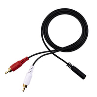
- RCA (Radio Corporation of America) connectors are used in consumer audio equipment, including CD players and home theater receivers.
Unbalanced connections are more prone to noise over longer runs because the shield carries both the ground reference and the return signal simultaneously. Any noise current induced into the shield adds directly to the audio signal with no cancellation mechanism available.
A balanced connector does not grant you a balanced signal. The equipment on both ends must support balanced operation for common-mode noise rejection to function.
Ground loops: a common cause of hum
A ground loop occurs when two or more connected devices share several ground paths at slightly different electrical potentials. That voltage difference drives a small current through the signal path, creating a persistent hum at the mains frequency, typically 50 or 60 Hz. Balanced connections lessen this problem because the differential receiver rejects common-mode noise. Ground loops can still occur in balanced systems when the common-mode voltage between ground points exceeds the receiver's rejection capability, which is why power distribution and equipment placement remain relevant.
Expert Tip: Keep your unbalanced runs short whenever possible. Use balanced lines for longer runs.
Analog vs Digital Audio
Analog cables accumulate noise and lose signal as their length increases. Digital cables operate under a different principle. A digital link either delivers the data intact or it fails. When it fails, you get clicks, dropouts, or complete signal loss, not a gradual tonal change. The gradual tonal changes that concern users with analog cables do not apply to digital transmission.
Optical vs coaxial S/PDIF: practical differences
Sony/Philips Digital Interface (S/PDIF) is a consumer digital audio format available in two forms.
Optical S/PDIF transmits data as pulses of light through a plastic optical fiber cable. It is immune to electromagnetic interference (EMI) and eliminates the electrical ground connection between devices, preventing ground loops. Optical cables can suffer signal loss or dropouts if you bend them too sharply. Repeated tight bends can also damage the fiber over time, so follow a reasonable bend radius at installation points.
Coaxial S/PDIF uses an electrical signal over 75-ohm coaxial cable and performs reliably across typical residential and studio distances. S/PDIF coax is specified for 75-ohm cable. Some RCA cables are not 75-ohm and may cause issues.
HDMI audio: when cable issues show up
High-Definition Multimedia Interface (HDMI) carries high-speed digital data, including audio. When the cable or connector is marginal, audio dropouts, pops, or handshake failures can occur when devices switch between audio formats or sample rates. Cable length, tight bends, and worn connectors are the most common contributing factors. A shorter cable with a cleaner routing path resolves the majority of HDMI audio faults without equipment changes.
Expert Tip: With digital audio faults, replace the cable with a shorter, known-good unit and verify routing before adjusting device settings. Physical cable conditions cause most digital audio faults in field installations.
When Audio Cables Can Make a Real Difference
A correctly specified and properly terminated cable of the right type will not alter the tonal character of a well-designed audio system under normal conditions. Audible differences appear when a cable is too long for the application, insufficiently rated for the current it carries, inadequately shielded for the interference in the environment, or poorly terminated at either end. Identifying which of those conditions applies points directly to the corrective action.
Do audio cables affect sound quality in your setup?
The conditions below are the most reliable indicators that a cable is contributing to an audible problem. Verify these before investigating other parts of the signal chain.
- You have a long unbalanced run routed near electrical equipment, power adapters, or AC cabling.
- You are using thin speaker cable over a distance greater than a few meters with a low-impedance speaker load.
- You have a passive high-impedance source, such as a guitar pickup, feeding a long cable run.
- Your connectors feel loose, or the sound changes when you apply pressure to the plug.
If none of those conditions applies to your installation and you still notice a difference between the cables, there is most likely a difference in output level. A cable that delivers a slightly higher signal will seem better to most listeners, even if the tonal content is identical. If you match the volume before comparing, you probably will not perceive the difference anymore.
Speaker runs: gauge, length, and load in real rooms
Low-impedance speakers draw more current from the amplifier. Long runs of small speaker cable increase series resistance to that current path, which cuts output level and can affect low-frequency control. For 8-ohm speakers, 16 AWG cable is a dependable choice for runs up to 50 feet. Low-impedance loads of 4 ohms or below work better with 12 AWG or 14 AWG cable, especially over longer distances.
High-impedance sources: The importance of capacitance
Passive instrument pickups and some phono cartridge setups show high output impedance. They are more sensitive to cable capacitance than low-impedance line-level sources. An obvious drop in high-frequency clarity when you switch to a longer instrument cable indicates that cable capacitance is interacting with pickup impedance. Using a shorter cable, a lower-capacitance cable of the same length, or a buffer amplifier at the instrument output can resolve the problem.
Expert Tip: Before you replace anything, run a short test cable. If the problem disappears, the original cable was the cause. If it stays, the cable was never the issue, and you know you need to look elsewhere in the signal chain.
The Role of Installation Quality and Cable Management
How you install a cable is more important than which cable you buy. A well-specified cable that is poorly routed, badly terminated, or left without strain relief will underperform a basic cable that is installed correctly.
Keep signal cables separated from power adapters and alternating current (AC) cabling. Where crossings are unavoidable, route signal cables across power cables at a right angle to minimize parallel exposure and reduce interference coupling. Avoid sharp bends near connectors. Strain relief at each connector prevents the plug from carrying the cable's mechanical load, which loosens contacts and accelerates wear.
Quick install sequence for cleaner, quieter audio
A dependable installation sequence reduces errors and makes troubleshooting faster. Follow this order:
- Power off all equipment before connecting or disconnecting any cable.
- Seat each connector fully and confirm that there is no movement or wobble.
- Route your signal cables away from power cords, wall adapters, and AC distribution equipment.
- Add strain relief at each termination point so the plugs do not carry cable weight.
- Power on and listen for hum, buzz, or channel imbalance before finishing the installation.
Expert Tip: If you detect hum after a new installation, reroute the signal cables. Routing issues are a recurrent cause of hum.
Quick Troubleshooting Checklist for Hum, Buzz, and Dropouts
You can easily isolate cable problems if you change one variable at a time. The checklists below follow the most probable causes in order of likelihood for each type of symptom.
Hum and buzz
Hum and buzz are almost always caused by routing or grounding issues, not cable defects. Perform these checks in order before replacing any device.
- Lower the volume and mute inputs. Do this one at a time to identify the source of the noise.
- Move the cable away from the power adapters and AC cords. Listen for a change.
- Substitute a shorter cable on the same connection.
- If your equipment supports it, switch to a balanced connection end to end.
- Connect both devices to the same power strip and retest to eliminate ground potential differences.
One channel is cutting out or crackling
Intermittent channel faults suggest a mechanical error at a connector. The fault is almost always physical.
- Reseat both ends of the cable firmly.
- Swap both left and right cables at the source to determine if the fault moves with the cable.
- Check if there’s any looseness, oxidation, or physical damage in the plug.
- Replace the cable if the movement at the connector keeps making noise or causing dropout.
Digital dropouts
Digital audio does not degrade gradually as analog does. It works correctly, or it does not. When it fails, you hear clicks, dropouts, or silence. In most cases, a shorter cable with a cleaner route solves your problem.
- Substitute a shorter cable.
- Check for tight bends and mechanical tension at the connectors.
- Set devices to a fixed output format and test with automatic format switching disabled.
- Update device firmware if dropouts began after a software or settings change.
Expert Tip: Change one thing at a time. If you change several things at once, you will not know which one actually fixed the problem.
Common Myths About Audio Cables
Myths about audio cables persist because cable problems are very common. A ground loop hum that clears when you switch to a balanced connection, or a crackle that stops when you replace a corroded connector, makes you quite reasonably presume that cable changes produce audible results across the board.
Myth 1: "More expensive always sounds better"
Premium pricing can reflect better connector construction and longer-lasting materials, both of which are valuable factors. But this does not mean you will hear a difference. A regular-priced cable of the proper type, well terminated and appropriately connected between two devices, will perform as well as a more expensive option of the same specification.
Myth 2: "Gold-plated connectors improve audio"
Gold plating resists corrosion better than plain copper or nickel. In connectors that are repeatedly plugged and unplugged, or in humid environments, this oxidation resistance extends reliable contact life. Gold plating helps prevent corrosion and supports reliable contact over time. Therefore, the actual benefit is durability and long-term contact reliability, not acoustic performance.
Myth 3: "The cable direction changes the sound"
A passive cable has no directional electronics. Audio signal transmission is bidirectional. When a cable seems to sound different depending on its orientation, the more probable reason is a mechanical fault at one connector, a cold solder joint, or oxidation at a termination point. Verify those first before attributing the difference to cable direction.
Myth 4: "Digital cables need exotic materials to sound better"
A digital cable must meet the impedance specification of the format it carries and deliver data without errors. When both happen, the decoded audio is identical regardless of the cable's conductor material. When those conditions are not met, you’ll experience dropouts or total signal loss, but not an altered tone. Non-standard, alternative conductor materials do not change this relationship.
Expert Tip: Select the cable by type, impedance specification, and construction quality for the application. Durability is important for cables that are moved regularly. For fixed installations, correct specification and clean terminations should be the priorities.
Conclusion
Cables affect what you hear under specific, identifiable conditions. Any audio problem a cable can cause can be traced back to five factors: resistance, capacitance, shielding or routing (interference), connection type (balanced or unbalanced), and termination quality.
Each of these factors is measurable, and there’s a corresponding corrective action for each.
Test after test, and installation after installation, the conclusion is the same: how you install a cable and which connection type you use impact more than the brand you choose or the price you pay. An appropriately specified cable, cleanly terminated and correctly routed, is the standard you should aim for.
Match the cable type to the signal, keep your runs within the practical limits of the format, route your cables away from interference sources, and check your terminations. Build your system based on those basics, and replace doubt about the cables with doubt your cables.


Geben Sie als Erster einen Kommentar ab.
Hinterlasse einen Kommentar