Have you ever played the telephone game? The information cannot always be correctly transmitted in repeated retellings. So does data in telecommunication. Transmitting data accurately from one end of the cable to the other is not always easy. The quality of data transmission can be affected by components, operations, and external environments. Attenuation, or signal weakening can occur in both electrical or data transmission.
In telecommunication cabling, insertion loss is an essential parameter that impacts the overall cabling performance. In this blog, we’ll cover every detail about insertion loss and share tips to help you minimize it.
What is Insertion Loss?
Insertion loss (IL) refers to the signal loss in a transmission link caused by insertion of components in a copper or fiber optic link. It is a natural phenomenon that occurs in all types of signal transmission. The insertion loss measurement is usually expressed in decibels (dB) units.
Insertion loss is a crucial parameter in fiber optic and copper cabling. It is ideally a positive value indicating the ratio of signal loss by comparing input power to output power. Insertion loss can be tested using a DCM testing machine or Fluke tester.
The lower the positive dB, the better the performance. High insertion loss can significantly impact or even prevent the correct transmission of signals from one end to the other. Insertion loss is largely affected by the length and quality of the cable. It can also be affected by connection points like splices and connectors within a cable link.
Notes: What’s the difference between insertion loss and attenuation?
Signal attenuation refers to the overall signal loss as it travels via a medium, while insertion loss means the signal loss when the components are inserted into the communication system. These terms are actually the same thing and they are interchangeable in most cases. But “insertion loss” is more commonly used when testing the overall link with a tester.

Copper Cable Insertion Loss
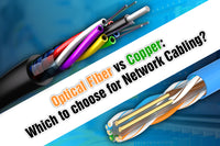
In copper cable, insertion loss is typically affected by the electrical resistance of the copper wire. As the signal travels through the copper cable, its attenuation varies with signal frequency. For example, the insertion loss of Category 5e and Category 6 cables can differ with their varying bandwidths. The high signal frequency will lead to great insertion loss. Copper cable insertion loss can also be caused by other factors:
- Cable Length: One of the primary factors affecting the copper cable insertion loss is the cable length. As the cable length increases, insertion loss also rises due to signal degradation over long distances,
- Wire Gauge: It is known that the smaller wire AWG indicates the thicker and greater conductive copper wire. Thicker copper wires typically have lower insertion loss than thinner types. For this reason, 28 or 27 AWG wires are often used for short-distance transmissions. Also, solid copper wires feature lower insertion loss than stranded ones, making them the best choice for long-distance cabling.
- Connector and Cable Quality: The quality of connector and cable can largely affect insertion loss. Higher-quality cables and connectors with better shielding can minimize insertion loss. Additionally, the conductor material plays a crucial role in signal transmission.
- Temperature: A high temperature can decrease the conductivity of the copper cable, leading to higher insertion loss.
- Moisture or Lubricant: The insertion loss can occur if the copper cable gets wet or if too much water-based cable lubricant is used. The lubricant used during installation is often highly conductive, causing electrons to dissipate and resulting in temporary high insertion loss until the lubricant cures.
Fiber Optic Insertion Loss
Compared to copper cables, fiber optic cables have low insertion loss. Single-mode fiber has lower insertion loss compared to single-mode fiber, so the former can carry light signals through a longer distance. Insertion loss in fiber optic cabling is influenced by the following factors:
- Inferior-Quality and Contaminated Fiber End Faces
One of the primary factors of fiber optic insertion loss is the quality and cleanness of fiber end faces. The contamination (particles) and improper cleaning of fiber mating surfaces can cause higher insertion loss.
- Fiber Misalignment
The two cores need to be perfectly aligned to ensure successful optical transmission. Otherwise, the misalignment of point-to-point connections between two jointed fibers can cause insertion loss.
- Excessive Bending
Too sharp or excessive bending of fiber, often due to incorrect operation or pressure, can cause light to escape from the core and cause insertion loss.
- Fiber Attenuation
The absorption and scattering of fiber naturally occur when light interacts with impurities or the molecular structure of the fiber. This fiber attenuation also adds to insertion loss.
Insertion Loss vs. Return Loss
Both insertion loss and return loss are two important measurement parameters in copper and fiber optic cabling. Though both of them are measured in dB, they represent different meanings.
As the above content mentions, insertion loss refers to the amount of signal loss over the cable link. Different from insertion loss, return loss measures the light power reflected back to the source. You know that a lower dB value means lower insertion loss. But return loss can be different: a higher return loss means lower reflection, indicating better performance. Poor return loss may degrade signal quality and cause noise.
How to Minimize Insertion Loss?
Although insertion loss is unavoidable, here are some tips for minimizing the loss.
Tips for Minimizing Copper Cable Insertion Loss
- Do not run copper cables over their maximum running length (100 meters or 328 feet). Keep copper cable runs as short as possible.
- Replace stranded copper with solid copper conductor at longer distances.
- Use cables or connectors with better shielding for lower insertion loss.
- Use keystone jacks that contains circuitry to ensure impedance matches.
Tips for Minimizing Fiber Optic Insertion Loss
- Use high-quality fiber connectors with low-loss components, ensuring efficient transmission.
- Regularly polish and clean the end face using the professional polishing and cleaning kit; inspect and clean fiber connector ferrules.
- Avoid excessive bending, stress, and tension.
- Minimize the number of splices or connection points if possible.
- Use adapters and compensation fittings to ensure precise alignment of fiber.
Final Thoughts
Insertion loss is an important measurement parameter to evaluate signal attenuation in telecommunications cabling systems. This blog introduces factors that affect insertion loss in optical fiber and copper cabling systems and offers some useful tips for minimizing insertion loss. You can implement correct installation and maintenance measures for your cabling. For more information and tips to optimize your network system, keep following our blog.
For more information on this topic, you can keep up on our blogs. While VCELINK offers general and basic information for our customers and other visitors to the website, it’s not professional advice.


Be the first one to comment.
Leave a comment