Though coaxial cables have seen a decline in popularity with the emergence of new alternatives like twisted pair cables and fiber optic cables, they once be regarded as a reliable choice for transmitting electrical signals with low data losses.
Coaxial cables have been a great companion over decades, powering television signals and Internet connections in people’s daily lives. These cables continue to find applications in older devices, and in this article, we’ll embark on the fascinating knowledge of coaxial cables.
Technical Terms About Coax Cable
Before knowing more about coaxial cables, here are some significant technical terms you should learn to understand better.
- Insertion loss: Attenuation or insertion loss is often measured in dB to indicate the loss of power. Attenuation can increase if the frequency increases.
- Bend radius: Bend radius is the radius at which a cable or tube can be bent without negative effects.
- Central conductor: It is the wire in the middle of a cable, and the wire can be solid or stranded. The conductor diameter is usually measured in American Wire Gauge (AWG).
- EMI: The full name of EMI is Electromagnetic interference. It is the unwanted noise or interference in an electrical circuit. EMI can affect the transmission of electrical signals.
- Impedance: Impedance is the resistance to the current electrical flow. The measure of impedance is Ohms.
- Frequency: The frequency used in coaxial is often referred to as “radio frequency”. Radio frequency is identified in Hertz (Hz).
- Dielectric: The dielectric is located between the central and outer conductor, which is an insulation allowing for electrostatic attraction and repulsion.
What is Coaxial Cable?
Coaxial cable, commonly known as coax cable, is a versatile electrical cable used in diverse applications. The invention of the coaxial cable can data back to the 19th century as Oliver Heaviside found the insulated cable could reduce signal loss and interference. Typically, a coaxial cable features a copper conductor surrounded by the insulation, and the insulation is wrapped by the second conductor called the shielding. The cable jacket servers as the outer layer. Do you know why it is called coaxial cable? The term means that the inner copper and second conductor share the same axis.
In the following sections, we’ll provide a brief overview of the four essential parts of a coaxial cable:

- Central Conductor: The inner conductor is usually made of solid or stranded wires, which is an important part of data transmission.
- Insulation: The dielectric insulation helps separate the central conductor and shielding
- Shielding: The shielding is also regarded as the second conductor of the coaxial cable, which is often the mesh or mesh and foil braiding. The shielding is designed to protect electrical signals from electromagnetic interference.
- Cable Jacket: The protective plastic jacket is usually made of PVC and protects the inner layers from external damage.
How do Coaxial Cables work?
The working principle of coaxial cables is quite complicated, and we’ll briefly introduce it in this article. The coaxial cable features an inner conductor and an outer conductor. The inner conductor transmits electric signals, and the outside can restrict the signal’s magnetic fields to the dielectric layer. The outside magnetic fields are also prevented from interfering with the inside signal transmission. The coaxial cable can be regarded as a waveguide, and its electric and magnetic power is mainly transmitted in transverse electric magnetic (TEM) mode.
Waveguide Modes: Electromagnetic waves can travel through waveguide in different modes. There are three main waveguide modes: TE, TM, and TEM.
- Transverse Electric Wave (TE mode): Also named as H mode. In this mode, the electric field is always perpendicular to the direction of propagation.
- Transverse Magnetic Wave (TM mode): Also known as E mode. In this mode, the magnetic field is purely perpendicular to the direction of propagation.
- Transverse Electric Wave Mode (TEM mode): In this mode, electric and magnetic fields are perpendicular to the direction of propagation. It is the mode often used in coaxial and open wires.
Coaxial Cable Types
Coaxial cables come in various types for specific applications and requirements. These cables also have different characteristic impedances, but most coaxial cables on the market have an impedance of 50 or 75 Ohms (Ω). 50 Ohm and 75 Ohm coax cables have different applications.
50 Ohm coax cables are more powerful than 75 Ohm cables and are often used for two-way radio frequency transmission. 50 Ohm cables are generally suited for industrial and commercial applications involving higher power, such as wireless communication systems and RF testing and measurement.

75 Ohm cables are designed to have a lower signal loss, making them suitable for audio and video applications such as CATV and satellite TV installations, CCTV systems, and some broadband Internet applications.

Here are some common coaxial cables used on the market:
- RG-6 Cable: RG-6 is a ubiquitous coaxial cable in daily life. An RG-6 cable usually has an impedance of 75 Ohms, which is widely used for cable television, satellite, and other professional video applications. RG-6 cables are similar to RG-59 cables and can provide better signal quality over a longer distance.
- RG-11 Cable: RG-11 cables are thick cables with low attenuation levels, meaning they can transmit radio frequency over long distances. But RG-11 cables are challenging to operate with.
- RG-58 Cable: RG-58 cables usually have an impedance of 50 or 52 Ohms. RG-8 cables are often used for short-distance Ethernet networks.
- RG-59 Cable: RG-59 also has an impedance of 75 Ohms but a thinner AWG than RG-6 cable. RG-59 cables are often found in older installations like cable modems and analog video systems. Compared to RG-6 cables, RG59 has a lower bandwidth, so it is less suitable for high-definition applications.
- RG-8 Cable: RG-8 cables have an impedance of 50 Ohms. RG-8 coaxial cables are thicker and more robust than RG58 cables, suitable for radio antennas, radio stations, and other applications that require high power.
- RG-213 Cable: RG-213 cables also have an impedance of 50 Ohms. RG-213 cables are similar to RG-8 cables and are often used for professional and amateur radio applications.
- RG-316 Cable: RG-316 cables are known for their lower signal loss and flexibility. It can be used for LAN and WAN applications.
Tip: Coaxial cables are known as Radio Frequency (RF) cables. RG stands for “Radio Guide,” once specified for military use.
Coaxial cables can also be classified into semi-rigid and formable types based on their flexibility and construction. Do you know the differences between them?
- Semi-rigid coaxial cable: The semi-rigid cable is also known as “hard-line” coaxial cable. It is a coaxial type with a more solid shielding than woven braid, making it ideal for higher frequency applications. The stable performance makes this coaxial cable suitable for RF and microwave applications. Semi-rigid coaxial cables are also perfect for various high-temperature applications. However, it is tough to bend them by hand, and a professional tool is needed if you want to turn them into your desired shape.
- Formable coaxial cable: The formable wires are manufactured with a tin-filled copper outer conductor, which can be more flexible than semi-rigid cables. This coaxial cable can be bent easily by your hand while keeping its performance so that it can be more expensive.
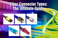
Coaxial Cable Connector
Various coaxial cable connectors are available to be used with different coaxial cables. We list several common coax connectors in this article.
BNC Connector
Developed in the 1980s, Bayonet Neill-Concelman (BNC) connectors are one of the most common coaxial cable connectors. The simple bayonet-style connector ensures a quick and reliable connection. BNC connectors come in both 50 and 75 Ohm types, ideal for radio and RF applications such as RF test equipment and audio and video transmission systems.
SMA/SMB Connector
The Subminiature Version A (SMA) connector was developed in the 1960s with a simple screw-type coupling style. Most SMA connectors come in 50 Ohm types and are often used with RG-58 cables. SMA connectors are great for high-frequency applications such as RF applications, GPS antennas, and Wi-Fi antennas.
SMB connectors are smaller than SMA connectors, which feature a snap-on style. SMB connectors are also used for high-frequency applications with a maximum transmission of 4 GHz.
TNC Connector
The full name of TNC is Threaded Neil-Concelman, and TNC coaxial connectors are an upgraded version of BNC connectors. These coaxial connectors use threads to reduce leakage. The obvious feature of the TNC connector is its water resistance, making it suitable for outdoor applications. Typical applications of TNC connectors are cell towers and RF antennas.
MCX Connector
Micro coaxial connectors were created in the 1980s and are smaller than SMB connectors. MCX connectors feature a snap-on style for easy installation. MCX connectors are generally used for digital systems, GPS, and RF equipment.
F Connector
F-type connectors were invented in the 1950s and can be found on your televisions. F connectors are used with RG-59, RG6, and RG11 coaxial cables and are often applied in satellite televisions and cable modems.
RCA Connector
Radio Corporation of America (RCA) connectors are commonly used for audio and video applications. They are popular for their low cost and availability. You can often find RCA connectors on your televisions, digital cameras, and stereo systems.
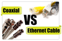
Coaxial Cable vs Twisted Pair Cable vs Fiber Optic Cable

Coaxial, Ethernet, and fiber optic cables are three distinct types of cables used for different purposes. They can be used to transfer television, telephone, and network data, but there are some differences among them. Both coaxial and twisted pair cables feature copper wires surrounded by insulation to transmit signals, but fiber optic cable uses thin strands of glass or plastic fibers to transmit data. Compared to coaxial cables and twisted pair cables, fiber optic cables can deliver the same signal with faster speed, higher frequency, and less interference.
In general, twisted pair cables are used for telephone or data networks; coaxial cables are designed for cable televisions, digital audio, and computer network connections; and fiber optic cables for long-distance data delivery or last-mile FTTx applications.
Nowadays, coaxial cables have been gradually replaced by twisted pair cables and fiber optic cables in network installations, and fiber optic cables seem to be future trend to meet the increasing demand of high network speed. However, whether to choose coaxial cables, twisted pair cables, or fiber optic cables depends on your applications, budgets, and desired performance.
For more information on this topic, you can keep up on our blogs. While VCELINK offers general and basic information for our customers and other visitors to the website, it’s not professional advice.

Fantastic and interesting essay!
Coaxial cables are essential components of RF and communication systems, offering good shielding and regulated impedance for consistent signal transmission. Their low electromagnetic interference and signal loss make them excellent for antennas, RF modules, telecom equipment, and testing applications.
Eteily Technologies manufactures and distributes high-quality coaxial cables and RF cable assemblies that are designed for low attenuation, good shielding efficacy, and long-term durability. Our technologies are widely used in telecom, Internet of Things, GPS, and wireless communication systems.
Thank you for providing great insights for engineers and professionals working with RF connectivity solutions. 📡
Hi. your blog helped me to figure out my problem with dell charger cable. I thought that I got a splice in the middle of the cable because it connects when I bend the cable randomly in the middle of cable between ferret and adpater. I saw this blog and I checked if there might be a disconnect right off the adapter. Indeed it did. I have not bend this part. But I am not sure how it got disconnected. I soldered it back and it works.
Thanks.
I really enjoyed reading it as it is a clear and simply explained theory.
thank you.